
|
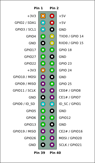
Raspberry Pi contains several GPIO pins, which can be used as digital input or outputs (GPIO = General-purpose input/output). For example, if GPIO4 is defined as output, then setting the output value to 1 provides 3.3V into that physical pin 7. If GPIO4 is defined as input, then it can read values 0 or 1. Value 1 means that there is a voltage detected on the physical pin 7. The same physical connector also has pins for other interfaces, for example for a serial interface SPI. (MOSI, MISO, SCLK). The physical pins for SPI are 19, 21, 23-26. SPI is usefull for reading analog values from outside world via ADC (Analog-to-digital converter). Some ADC chips contains the SPI and can therefore be directly used with Raspberry Pi. |
|
However, if one wish to connect Raspberry Pi with physical devices, it is easier to buy one of the expansion boards. For example, Gertboard.
In this blog, we take a simple look on some examples and are using python for programming. Please see RPi GPIO Code Samples for more details on programming languages available, for example wiringPi is very widely used from different programming languages.
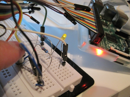
Using push button to turn on LED
This is demonstrating on how to use GPIO. This is following the instructions: Reading and writing from GPIO ports from Python.
Main components:
- push button, 1 LED, 2 resistors (800 ohm), (GPIO connector cable)
The interactive python, ipython, was used with the following code:
import RPi.GPIO as GPIO
GPIO.setmode(GPIO.BCM)
GPIO.setup(4, GPIO.IN, pull_up_down=GPIO.PUD_DOWN)
GPIO.setup(25, GPIO.OUT, initial=GPIO.LOW)
GPIO.add_event_detect(4, GPIO.BOTH)
def my_callback(channel):
   GPIO.output(25, GPIO.input(4))
GPIO.add_event_callback(4, my_callback)
Note, GPIO4 is physical pin 7, and GPIO25 is physical pin 22.
When change is detected on GPIO4, then my_callback is executed and output of GPIO25 is set to same value as is read from GPIO4.
After each run, it is good to give command GPIO.cleanup()
Measuring the temperature
In this case ADC is used to measure the output voltage from a temperature sensor. The value from ADC is read via SPI.
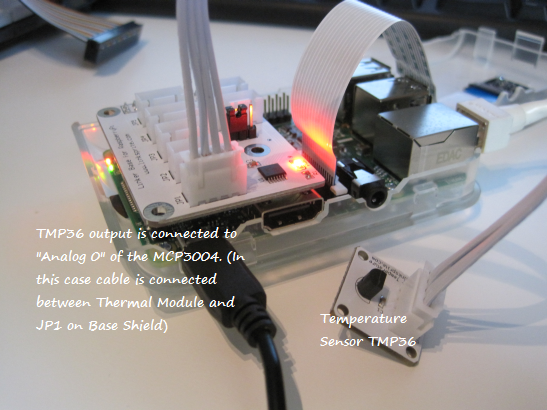
Local PC store had components from linksprite. The instructions at the manufacturer site are followed: How to use Linker kit Base Shield for Raspberry Pi with ADC Interface with Python Code. (It is possible to make this test by using TMP36 and MCP3004 directly instead of using ready made components)
- Thermal Module, containing a low voltage temperature sensor TMP36.
- Base Shield, containing an ADC MCP3004
The original instructions were giving voltage values. The code was modified to get both voltages and temperatures:
import spidev
import time
import datetime

adc_channel = 0
spi = spidev.SpiDev()
spi.open(0,0)

def readadc(adcnum):
# read SPI data from MCP3004 chip, 4 possible adc's (0 thru 3)
  if adcnum >3 or adcnum <0:
     return-1
  r = spi.xfer2([1,8+adcnum <<4,0])
  adcout = ((r[1] &3) <<8)+r[2]
  return adcout

while True:
    value=readadc(adc_channel)
    volts=(value*3.3)/1024
    ts = time.time()
    st = datetime.datetime.fromtimestamp(ts).strftime('%Y-%m-%d %H:%M:%S')
    print st
    print("SPI: %4d/1023 => %5.3f V" % (value, volts))
    temp=(1000*volts-500)/10
    print("                = %4.1f degree C" % (temp))
    print("-----------------------------------------------------")
    time.sleep(5)
When executed, it gave the following printout
pi@raspberrypi ~ $ python ./temperature.py
2015-07-05 17:22:10
SPI:  231/1023 => 0.744 V
                = 24.4 degree C
-----------------------------------------------------
2015-07-05 17:22:15
SPI:  231/1023 => 0.744 V
                = 24.4 degree C
-----------------------------------------------------
Please note, that the reading from serial interface (SPI) is done with the command spi.xfer2().
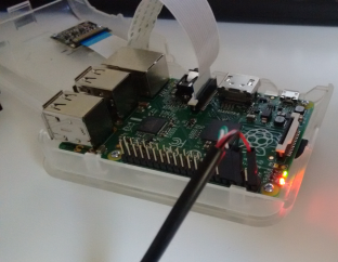
Serial connection to Raspberry Pi
Raspberry Pi’s GPIO contains pins for serial communication, and it can be used to connect to the operating system. An USB TTL cable was used. The instructions from Adafruit’s Raspberry Pi Lesson 5. Using a Console Cable were used. Please note that RS232 and TTL has different voltages. (If you intend to use USB-RS232 cable, then an additional RS232-TTL converter is needed as well.)
Continuation
Please see part 2.