
This blog continues from the previous blog Raspberry Pi and physical interfaces.
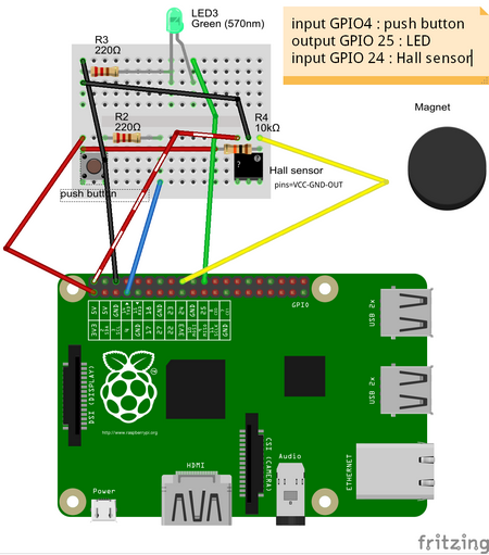
Case: GPIO with 1 LED output and 2 inputs
First the push button & LED example is modified to include also another input, a hall switch. For the documentation, tool called fritzing is used. For the example source code, please see blog.
This is based on the sources:
These 2 separate tests were combined into one. If either push button is pressed or if the magnet comes close, then LED is turned on. Source file “test-buttonledhall.py” is shown below. In this case while loop is used instead of callback function. Hall switch used (TLE4905L) is unipolar, ie. reacts only to one magnetic pole, and “conductivity” is opposite (see datasheet).
#!/usr/bin/env python

try:
 import RPi.GPIO as GPIO, time

 GPIO.setmode(GPIO.BCM)

 #inputs
 GPIO_PUSH_BUTTON = 4    # push button
 GPIO_HALL_SENSOR = 24   # Hall switch
 GPIO.setup(GPIO_PUSH_BUTTON, GPIO.IN, pull_up_down=GPIO.PUD_DOWN)    # push button
 GPIO.setup(GPIO_HALL_SENSOR, GPIO.IN, pull_up_down=GPIO.PUD_DOWN)   # Hall switch
 hallActive  = False

 #outputs
 GPIO_GREEN_LED   = 25   # LED
 GPIO.setup(GPIO_GREEN_LED,   GPIO.OUT, initial=GPIO.LOW)            # LED
 LEDActive   = False

 while True:
    if( GPIO.input( GPIO_PUSH_BUTTON ) == True ): LEDActive = True

    if( GPIO.input( GPIO_HALL_SENSOR ) == False ): LEDActive = True

    if( GPIO.input( GPIO_PUSH_BUTTON ) == False and GPIO.input( GPIO_HALL_SENSOR ) == True ): LEDActive = False

    GPIO.output( GPIO_GREEN_LED, LEDActive )
    time.sleep( 0.300 )


finally:
    print('cleanup...')
    GPIO.cleanup()
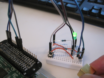
Photo and video are available.
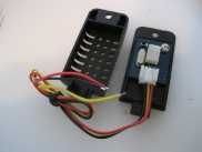
Case: GPIO single-bus communication: humidity & temperature sensor AM2301 (DHT21)
Sources:
Links:
- Adafruit DHTxx sensors
- Other ways: DHT21 with wiringpi, Grove – Temperature and Humidity Sensor (I did not test these)
The digital communication with this sensor is more complex. In the datasheet, it is described as single bus communication. The 0’s and 1’s are not communicated by voltage, but by timing (in microseconds) on how long the voltage stays up (see C source code for more information). Luckily the link above contained a link to an executable. The purpose was to do a quick test if this sensor can be used with Raspberry Pi, and yes it works.
The execution was done with DHT22 or AM2302 as parameter
pi@raspberrypi ~ $ sudo ./Adafruit_DHT 22 4
Using pin #4
        Data (48): 0x1 0xcd 0x0 0xf1 0xbf
Temp =  24.1 *C, Hum = 46.1 %
pi@raspberrypi ~ $ sudo ./Adafruit_DHT 2302 4
Using pin #4
Data (48): 0x1 0xc8 0x0 0xf4 0xbd
Temp =  24.4 *C, Hum = 45.6 %
pi@raspberrypi ~ $ sudo ./Adafruit_DHT 22 4
                Using pin #4
Data (48): 0x1 0xc9 0x0 0xf2 0xb4
I opened the cover, but unfortunately the connector is not compatible (inch vs metric systems).
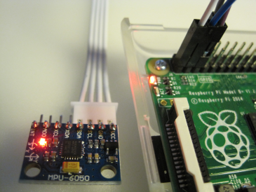
Case: I2C: Gyroscope and Accelerometer readings (MPU-6050)
In this case we are following a set of instructions (see Sources below):
Sources:
- Interfacing Raspberry Pi and MPU-6050
- Reading data from the MPU-6050 on the Raspberry Pi
- 3D OpenGL visualisation of the data from an MPU-6050 connected to a Raspberry Pi
- Using a complementary filter to combine Accelerometer and Gyroscopic data
Links:
- MPU-6050 Accelerometer + Gyro
- Arduino MPU 6050 – Best IMU Sensor Tutorial
- MPU-6050 sensor connected to Raspberry Pi
Verifying I2C connection:
pi@raspberrypi ~ $ sudo i2cdetect -y 1
     0  1  2  3  4  5  6  7  8  9  a  b  c  d  e  f
00:          -- -- -- -- -- -- -- -- -- -- -- -- --
10: -- -- -- -- -- -- -- -- -- -- -- -- -- -- -- --
20: -- -- -- -- -- -- -- -- -- -- -- -- -- -- -- --
30: -- -- -- -- -- -- -- -- -- -- -- -- -- -- -- --
40: -- -- -- -- -- -- -- -- -- -- -- -- -- -- -- --
50: -- -- -- -- -- -- -- -- -- -- -- -- -- -- -- --
60: -- -- -- -- -- -- -- -- 68 -- -- -- -- -- -- --
70: -- -- -- -- -- -- -- --

pi@raspberrypi ~ $ sudo i2cget -y 1 0x68 0x75
0x68
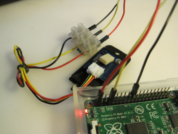
The picture below shows the sensor and 4 cables used to connect it with Raspberry Pi.
Copying the source code into gyro.py, and executing it (for the source code, see links above):
pi@raspberrypi ~ $ sudo ./gyro.py
gyro data
---------
gyro_xout:  -141  scaled:  -2
gyro_yout:  328  scaled:  2
gyro_zout:  63  scaled:  0

accelerometer data
------------------
accel_xout:  4628  scaled:  0.282470703125
accel_yout:  -296  scaled:  -0.01806640625
accel_zout:  15256  scaled:  0.93115234375
x rotation:  -1.06367143706
y rotation:  -16.8724967644
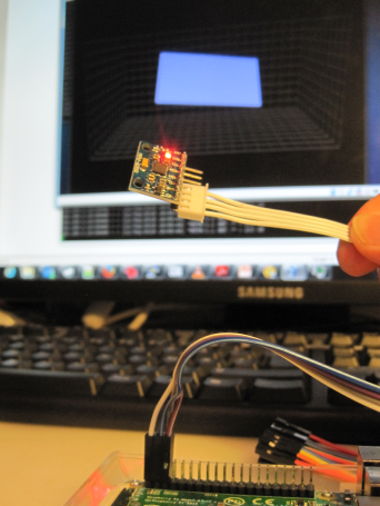
After this, xubuntu VM was used to execute the OpenGL 3D program (level.py) to demonstrate the orientation.
Conclusion
Already “now” there are several working examples for testing and playing with “Internet of Things” 🙂 . Well, here “now” actually means 2-3 years back. Now there is even more complex examples. But to get started, it is good to start from the basics…