Once, when taking outside photos, the digital camera (Canon SX1) started to get problems. I hadn’t thought about it much earlier, but obviously -18 degree Celsius was too much for the electronics.
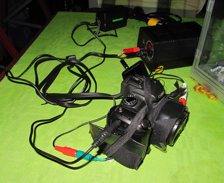
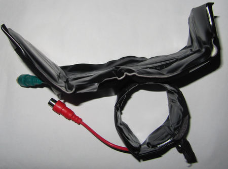
Quick search on internet showed several DIY heater plans where simple resistors were used. Since I happened to have several 0.6W resistors and a variable power source, I tried to solve the camera heating issue with those first. The photo below shows the solution, one heater stripe under the frame, and second heater stripe on objective.
Alternative solution is to buy following main components:
-
12V power supply
-
12V dimmer to control the power applied to the heater
-
resistive wire, like kanthal, for the objective and frame heater
-
(optionally power resistor for the frame heater)
Time will tell, but after the first tests, the simple resistor approach seems to work.
Generating heat via resistance
The following formulas can be used
- Current I=U/R
- Voltage U = I*R
- Power P = U*I
So for example. if one estimates that max 10W is sufficient for the digital camera, then:
- the current requirement for the 12V power supply I=P/U = 10W/12V= 0.8A
- the resistance is R=U/I = 12V/0.8A= 15ohm
When the solution is build from normal 0.6W resistors, then one at minimum one would need 10W/0.6W=17 resistors in optimal case. However, it is safer to limit the power to 0.4-0.5W per resistor in the calculations. With 0.4W per resistor, then in optimal case, it takes 25 resistors.
Solution photos
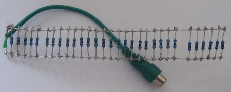
Frame heater:
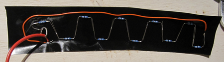
Objective heater:
Both together after taping and some insulation:
Heating test
Luckily, the thermometer values in camera are available via CHDK.
After 2 hours outside, the camera temperature was about 0.

After about 1 hour heating with full power, the temperature was increased almost 30 degrees.

Now it looks promising to be able to take some photos outside during the winter 🙂
Solution calculations
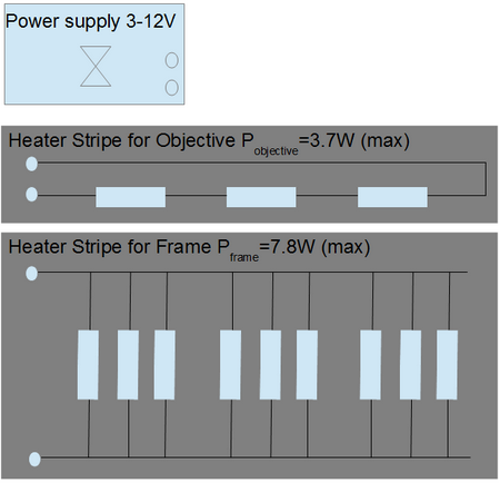
With the resistors in hand, 10 resistors were used to Objective heater stripe, and 30 resistors for Frame heater stripe. The maximum heating powers are 3.7W and 7.8W, respectively. The power was controlled by a 12V/24W power supply.
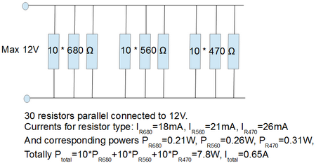
The calculations for parallel connected resistors is quite straightforward. Each resistor have to “survive” 12V without breaking. In the planning phase, one could calculate the total resistance, but it is quite easy to skip that calculation, and calculate the power for each resistor separately. Just add more resistors, until you get the power you need. The figure below shows the 30 resistor values used.
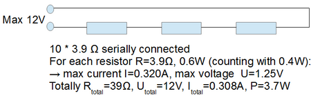
The calculations for the serial connected resistors is more complex. One cannot later add resistors in order to increase power. (Actually by increasing total resistance, the power is decreased; P= U2/R). Starting from the expected power, then one can calculate the rest. For example, to generate 4W in heat, the currentisI=4W/12V=0.3A. Then resistance is R=U/I = 12V/0.3A = 40ohm. If using 10 resistors with same value, then each resistor is R= 4ohm and have to sustainpowerP=4W/10=0.4W. The figure below shows the 10 resistor value used.
Prototype
The first attempt was to use lower voltage, ie. max 6V.
In this attempt 10*100 ohm resistors were connected parallel. For each resistor, the current is I=0,06A and power P=0.36W. The total power was therefore 10 times, ie. 3.6W. However, when the voltage was applied, it did not “feel” that it could heat properly, and then I decided to go to 12V. If one is having a 12V dimmer, then 12V can easily be taken from the car…