Short version
With an android phone and ODB adapter one can get access to the standardized diagnostic interface(s) of a car. I bought an ODB II bluetooth adapter to find out what information is available from a car. With a quick test of some android software, one could verify that some data is available. The data available is related to engine diagnostics.
List of items:
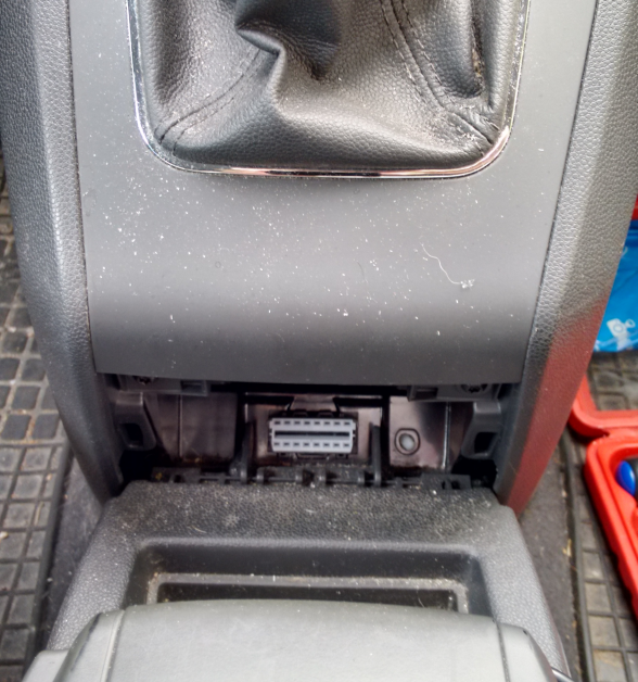
- Car with ODB II connector
- ELM327 ODB II bluetooth adaptor
- android tablet or phone
- ODB II software for android
| ODB II connector | ELM327 ODB II adapter |

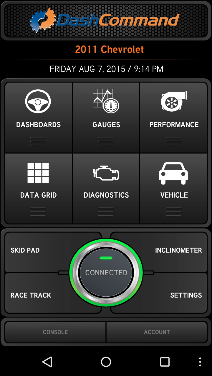
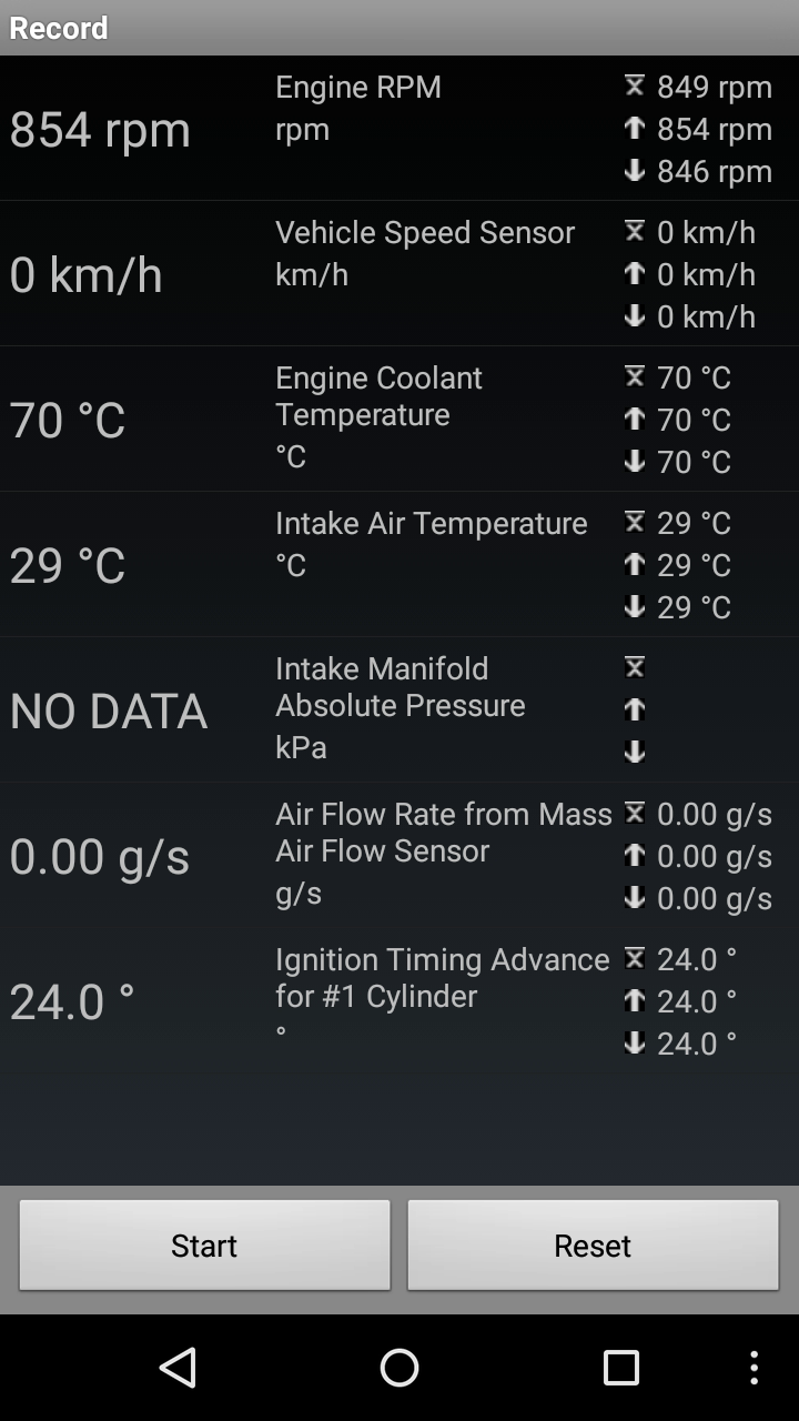
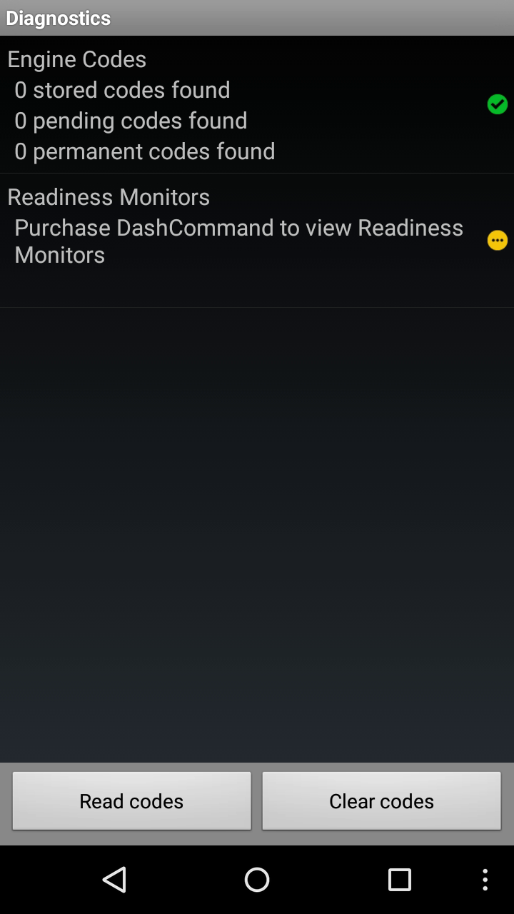
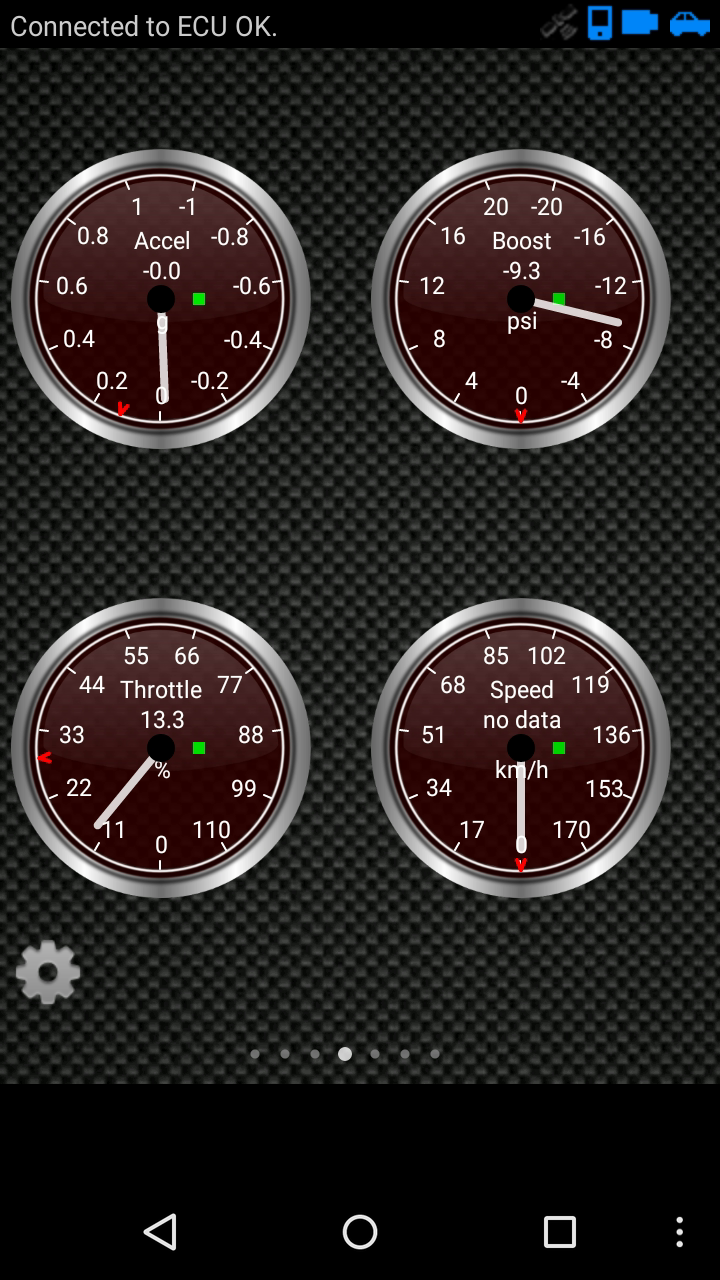
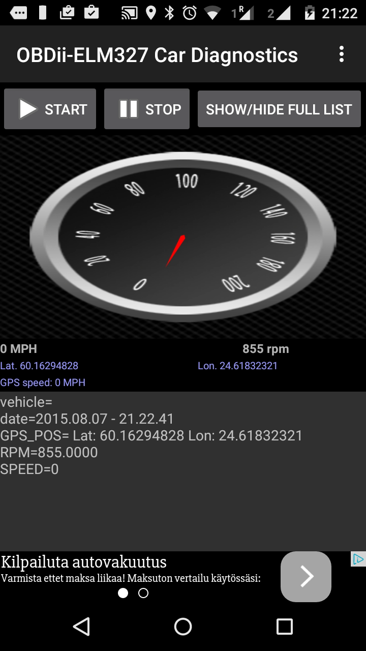
DashCommand provides a good looking interfaces with a lot of information, see below.
| Main view | Data grid provides some values over test period | Diagnostics would show any error codes, if there is any |
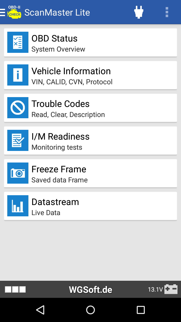
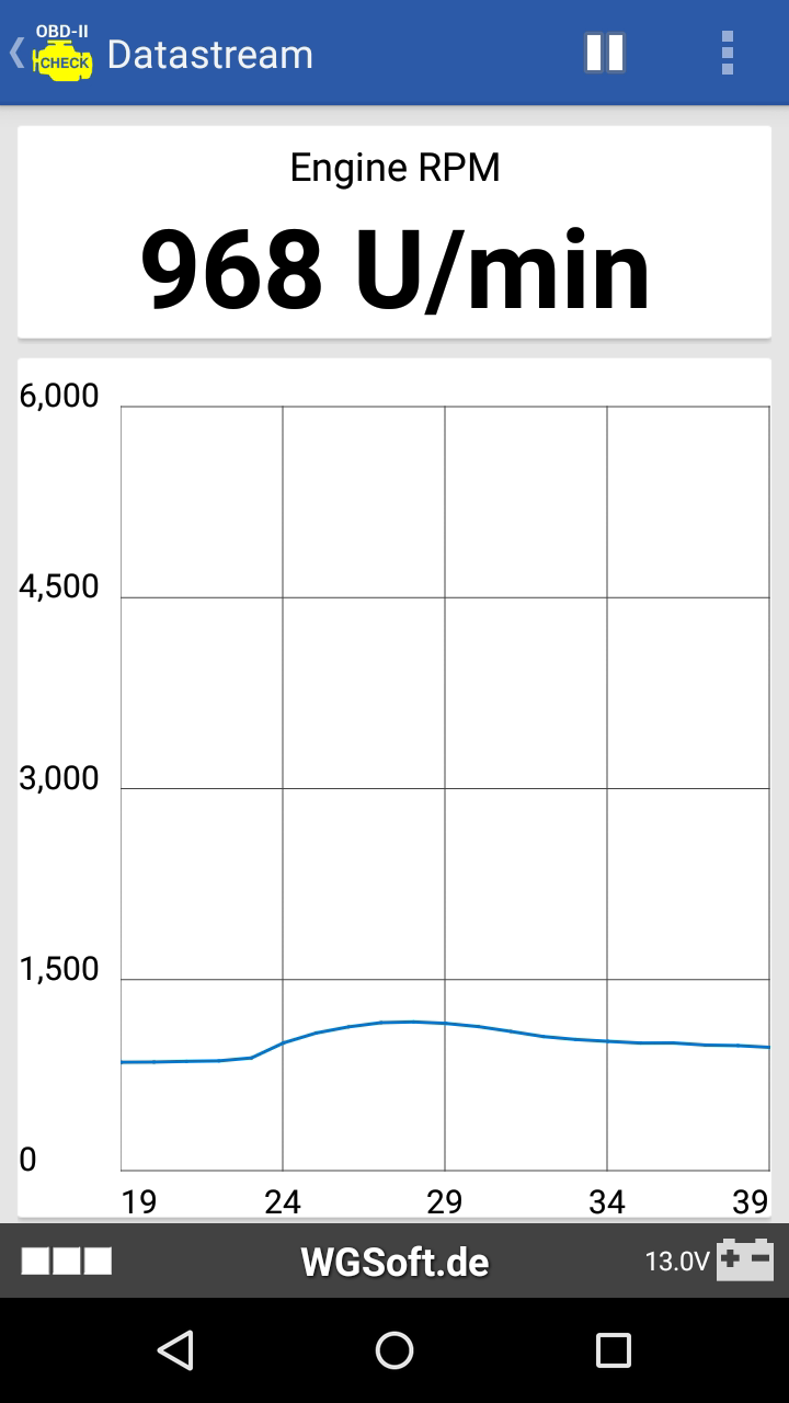
ScanMaster Lite was another impressive tool with a lot of information.
| Main view | VIN, CALID and CVN are available too (picture data is sanitized) |
RPM example |

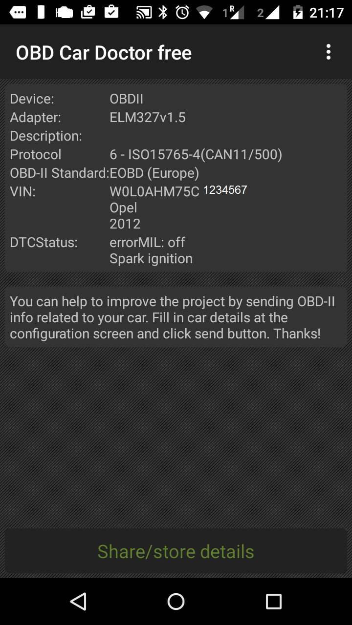
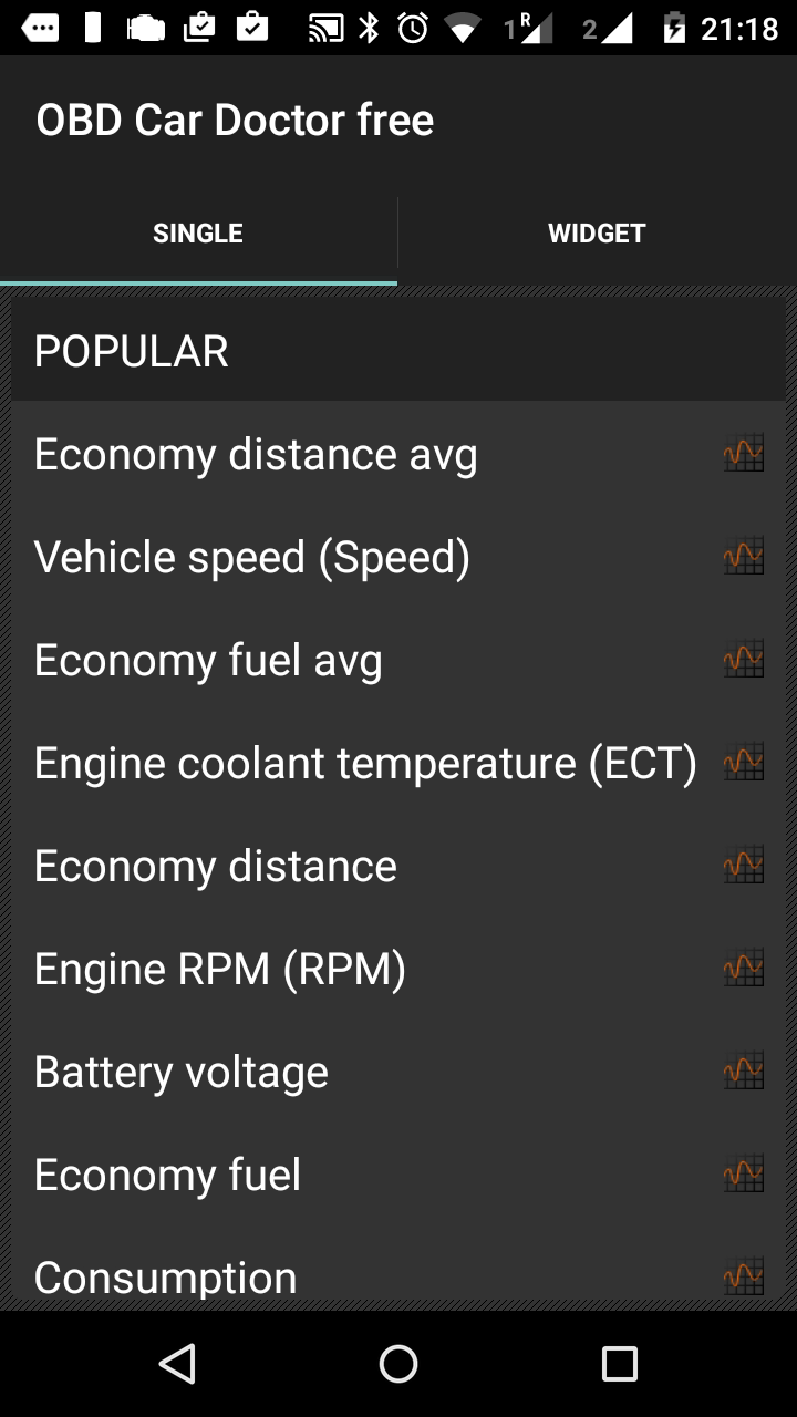
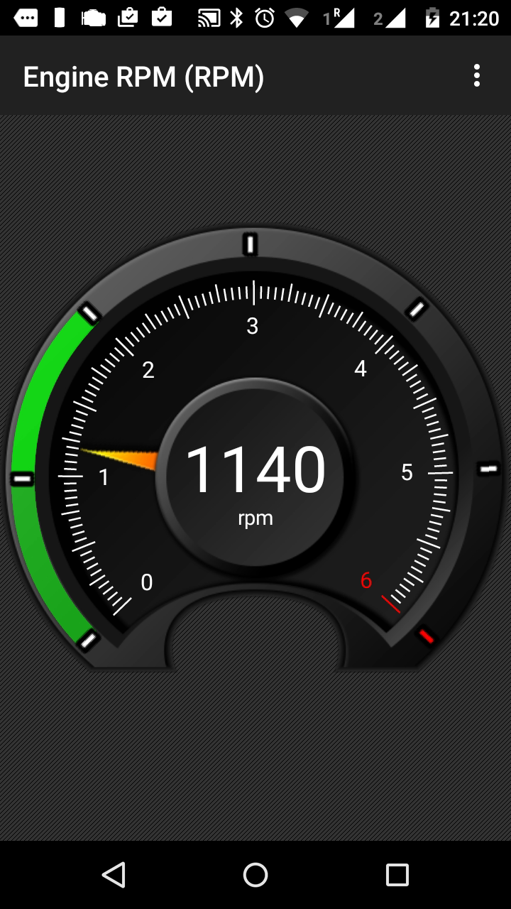
ODB Car Doctor free is another very informative tool.
| System overview | options in the menu | RPM meter |
Then there are other tools as well, which might provide some additional functions, or another look and feel.
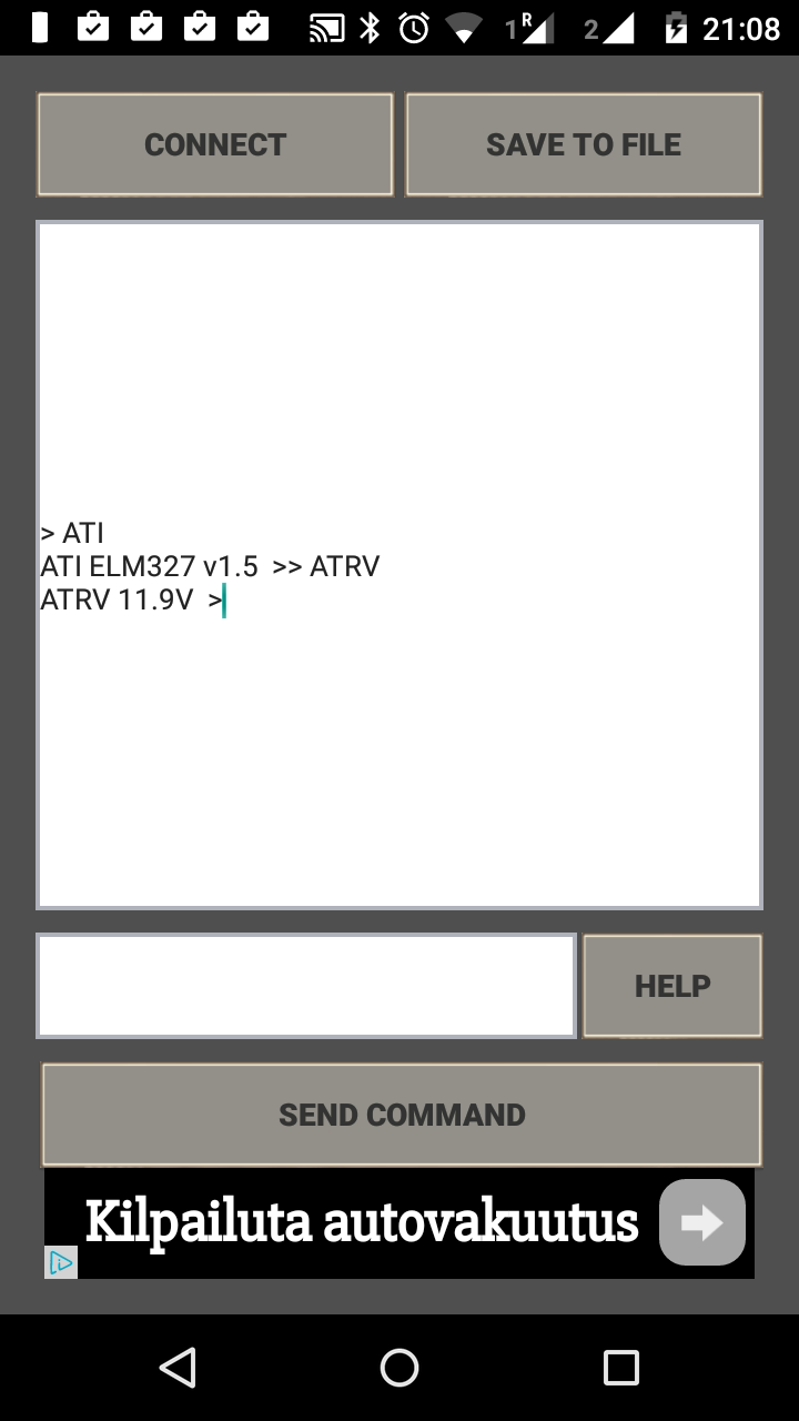
| Elm327 OBD Terminal – allows any AT command |
Torque – good looking interface |
Long version
Car contains much more digital information over several buses than what is accessable via ODB II…
On-board diagnostics (OBD) is an automotive term referring to a vehicle’s self-diagnostic and reporting capability.
OBD systems give the technician access to the status of the various vehicle subsystems.
OBD-II PIDs (On-board diagnostics Parameter IDs) are codes used to request data from a vehicle, used as a diagnostic tool.
ODB-II Connector
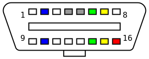
| Pin | Signal | Description |
| 2 | SAE J1850 Bus+ | |
| 4 | CGND | Ground (Chassis) |
| 5 | SGND | Signal Ground |
| 6 | CAN High | J-2284 |
| 7 | ISO 9141-2 K-LINE | Tx/Rx |
| 10 | SAE J1850 Bus- | |
| 14 | CAN Low | J-2284 |
| 15 | ISO 9141-2 L-LINE | Tx/Rx |
| 16 | +12v | Battery power |
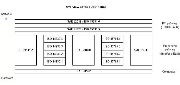
There are five diagnostics protocols in use with the OBD-II interface:
| Pins | Protocol |
| 2 & 10 | SAE J1850 PWM |
| 2 | SAE J1850 VPW |
| 7 & 15 | ISO 9141-2 |
| 7 & 15 |
ISO 14230 KWP2000 (Physical layer identical to ISO 9141-2) |
| 6 & 14 | ISO 15765 CAN |
These standardized protocols can be presented as layers. Why so many protocols? Good question. Anyway, these are alternative protocols meaning that one need to implement only one of the above mentioned protocols… (and luckily ELM 327 supports many protocols).
What information is available via ODB-II
In the standard interface, some specific information from engine control unit (ECU) has been made available and operation mode and parameter IDs are used to select and get the information. Some of the OBD-II modes of operation :
- 01 Show current data
- 02 Show freeze frame data
- 03 Show stored Diagnostic Trouble Codes
- 08 Control operation of on-board component/system
- 09 Request vehicle information
- Mode 01
-
- 03 Fuel system status
- 05 Engine coolant temperature
- 0A Fuel pressure
- 0C Engine RPM
- 0E Timing advance
- 0F Intake air temperature
- 11 Throttle position
- Mode 09
-
- 02 Vehicle Identification Number (VIN)
- 04 Calibration ID
- 06 Calibration Verification Numbers (CVN)
Good summary is available at OBD Modes.
The figure below “basic engine” might be usefull.
Which car support which diagnostics? There are several sources in internet with varying quality:
- Information on Opel Zafira (this site contains many other cars as well).
Please note that there are several other control units in the car, and these standards do not specify those.
CAN bus and control units
A controller area network (CAN bus) is a vehicle bus standard designed to allow microcontrollers and devices to communicate with each other in applications without a host computer. It is a message-based protocol, designed originally for multiplex electrical wiring within automobiles.
The CAN bus is simply a pair of wires, often twisted around each other, running around the vehicle and terminated at either end of the two-wire network with resistors of 120 Ohms. The only components connected to the CAN bus are the electronic control units (nodes). Other components, such as sensors, motors, light bulbs, switches, etc. are wired only to the electronic control units.
Some control units:
- Transmission control unit (TCU)
- Telematic control unit (TCU)
- Door control unit (DCU)
- ABS control unit
Other CAN buses (non ODB-II):
- Convenience CAN bus
- Infotainment CAN bus
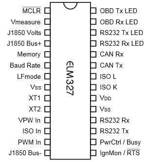
ELM 327
ELM 327 is a bridge device between ODB and RS232, and makes it possible to communicate with several protocols over serial connection (including bluetooth and wifi). The communication is done by using specific AT commands.
Other links
Some of this information is meant for security professional to know what’s up, as car hacking has been in the media more often…