Car on-board diagnostics (ODB II) with android, first tests

Short version

With an android phone and ODB adapter one can get access to the standardized diagnostic interface(s) of a car. I bought an ODB II bluetooth adapter to find out what information is available from a car. With a quick test of some android software, one could verify that some data is available. The data available is related to engine diagnostics.

List of items:

  • Car with ODB II connector
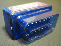
  • ELM327 ODB II bluetooth adaptor
  • android tablet or phone
  • ODB II software for android
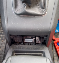
ODB II connector ELM327 ODB II adapter

odb-opel-zafira-b ELM327-adapter

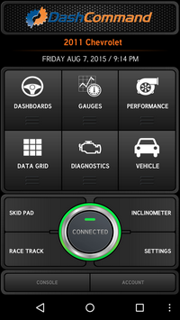
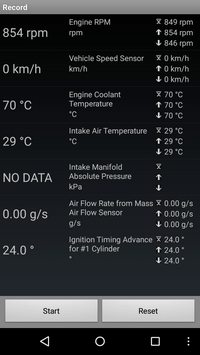
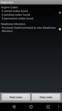
DashCommand provides a good looking interfaces with a lot of information, see below.

Main view Data grid provides some values over test period Diagnostics would show any error codes, if there is any

DashCommand1DashCommand2DashCommand3

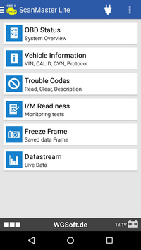
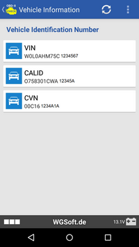
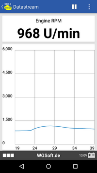
ScanMaster Lite was another impressive tool with a lot of information.

Main view VIN, CALID and CVN are available too
(picture data is sanitized)
RPM example

ScanMaster1ScanMaster2sanitizeScanMaster3

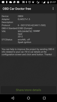
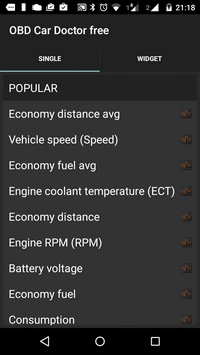
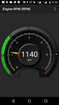
ODB Car Doctor free is another very informative tool.

System overview options in the menu RPM meter

ODB cad doctor1-sanitizeODB cad doctor2ODB cad doctor5

Then there are other tools as well, which might provide some additional functions, or another look and feel.

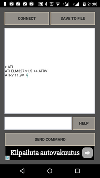
Elm327 OBD Terminal
– allows any AT command
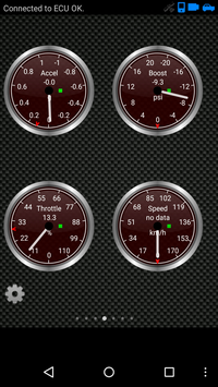
Torque
– good looking interface

Elm327 OBD TerminalTorque


Long version

Car contains much more digital information over several buses than what is accessable via ODB II…

Wikipedia:

On-board diagnostics (OBD) is an automotive term referring to a vehicle’s self-diagnostic and reporting capability.
OBD systems give the technician access to the status of the various vehicle subsystems.
OBD-II PIDs (On-board diagnostics Parameter IDs) are codes used to request data from a vehicle, used as a diagnostic tool.

ODB-II Connector

OBD connector shape svg

Pin layout and protocols :

Pin Signal Description
2 SAE J1850 Bus+
4 CGND Ground (Chassis)
5 SGND Signal Ground
6 CAN High J-2284
7 ISO 9141-2 K-LINE Tx/Rx
10 SAE J1850 Bus-
14 CAN Low J-2284
15 ISO 9141-2 L-LINE Tx/Rx
16 +12v Battery power

There are five diagnostics protocols in use with the OBD-II interface:

Pins Protocol
2 & 10 SAE J1850 PWM
2 SAE J1850 VPW
7 & 15 ISO 9141-2
7 & 15

ISO 14230 KWP2000

(Physical layer identical to ISO 9141-2)

6 & 14 ISO 15765 CAN

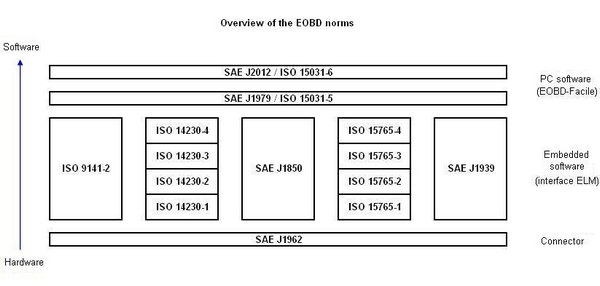
These standardized protocols can be presented as layers. Why so many protocols? Good question. Anyway, these are alternative protocols meaning that one need to implement only one of the above mentioned protocols… (and luckily ELM 327 supports many protocols).

norms-eobd

What information is available via ODB-II

In the standard interface, some specific information from engine control unit (ECU) has been made available and operation mode and parameter IDs are used to select and get the information. Some of the OBD-II modes of operation :

  • 01 Show current data
  • 02 Show freeze frame data
  • 03 Show stored Diagnostic Trouble Codes
  • 08 Control operation of on-board component/system
  • 09 Request vehicle information

Some Parameter IDs :

  • Mode 01
    • 03 Fuel system status
    • 05 Engine coolant temperature
    • 0A Fuel pressure
    • 0C Engine RPM
    • 0E Timing advance
    • 0F Intake air temperature
    • 11 Throttle position
  • Mode 09
    • 02 Vehicle Identification Number (VIN)
    • 04 Calibration ID
    • 06 Calibration Verification Numbers (CVN)

Good summary is available at OBD Modes.

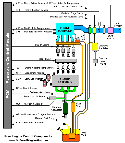
The figure below “basic engine” might be usefull.

becc

Which car support which diagnostics? There are several sources in internet with varying quality:

  • Information on Opel Zafira (this site contains many other cars as well).

Please note that there are several other control units in the car, and these standards do not specify those.

CAN bus and control units

A controller area network (CAN bus) is a vehicle bus standard designed to allow microcontrollers and devices to communicate with each other in applications without a host computer. It is a message-based protocol, designed originally for multiplex electrical wiring within automobiles.

The CAN bus is simply a pair of wires, often twisted around each other, running around the vehicle and terminated at either end of the two-wire network with resistors of 120 Ohms. The only components connected to the CAN bus are the electronic control units (nodes). Other components, such as sensors, motors, light bulbs, switches, etc. are wired only to the electronic control units.

Some control units:

  • Transmission control unit (TCU)
  • Telematic control unit (TCU)
  • Door control unit (DCU)
  • ABS control unit

Other CAN buses (non ODB-II):

  • Convenience CAN bus
  • Infotainment CAN bus

ELM 327

ELM 327 is a bridge device between ODB and RS232, and makes it possible to communicate with several protocols over serial connection (including bluetooth and wifi). The communication is done by using specific AT commands.
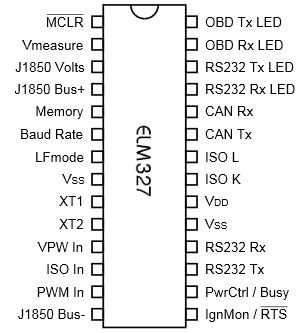
ELM327

Other links

Some of this information is meant for security professional to know what’s up, as car hacking has been in the media more often…

Posted in Android, DIY, For Fun or Interest, Gadgets, Hobbies and Other Interests, Internet of Things and M2M, Tests, Tools | Comments Off on Car on-board diagnostics (ODB II) with android, first tests

Cloud adaptation and security budget, reports by Microsoft and 451 Research

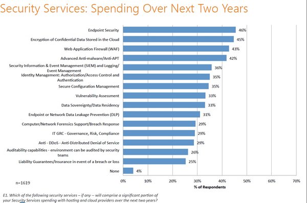
Microsoft has published interesting report, which contains information about security budget as well, good to know information for people working with information security management.

Beyond Infrastructure: Cloud 2.0 Signifies New Opportunities for Cloud Service Providers
Beyond Infrastructure- Cloud 2.0 Signifies Profit-Led Opportunities for Cloud Service Providers

451-research-01

451-research-03

Posted in Cloud Security, Security Management | Comments Off on Cloud adaptation and security budget, reports by Microsoft and 451 Research

Free vector graphics and icons by freepik

Freepik has made several vector graphics and icons available. Worth to take a look. Their icons are available also at flaticon.

In this blog, I try to make a short story by using freepik icons.

Please note that, icons are available also as vector, and in different colors and sizes. (Here I’m using size 512x, with html scaling down).

In the flaticon license terms, they ask to give a attribution: Icon made by Freepik from www.flaticon.com is licensed under CC BY 3.0

Short Story

Theclock9and Tom was still sleepy8. Today he would need tobusinessman87to get a black401early in the sunrise4.

In the destination, he took a trains. Tom could not access internet with his smartphones2, but he found a free wireless connectivity14 in order to connect to social network197. So he man462and girffriend female240both were smiley48for the new day.

But when Tom arrived to building6, his computer monitor1gave a warning exclamation34. He called customer service9, and explained the anti-virus message laptop computer15.

It took some time80, but after wrench105, Tom could continue with this agenda and finally managed to to his businessman83.

It seems that some criminal7had setup a rogue wifi criminal4 to steal credit71. Luckily thebugs3was recycle78.

Posted in Audio and Video, Basic Tools, For Fun or Interest, Hobbies and Other Interests, Recommended Free Tools, Tests, Tips | Comments Off on Free vector graphics and icons by freepik

Raspberry Pi and physical interfaces, part 2

This blog continues from the previous blog Raspberry Pi and physical interfaces.

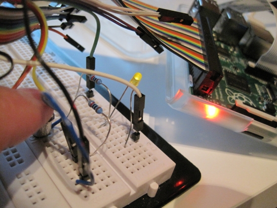
Case: GPIO with 1 LED output and 2 inputs

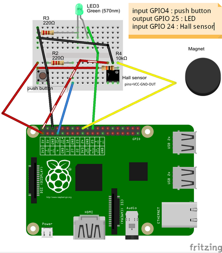
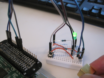
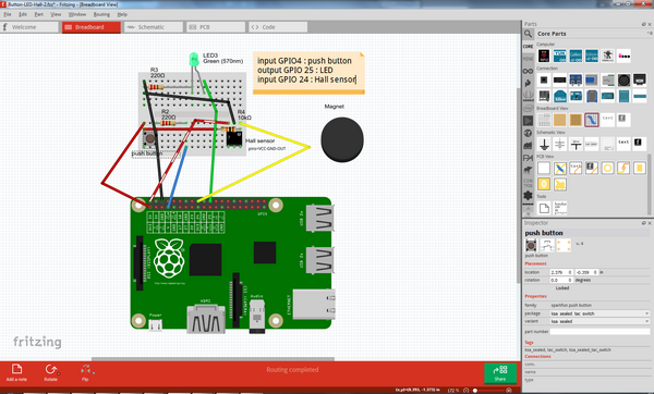
First the push button & LED example is modified to include also another input, a hall switch. For the documentation, tool called fritzing is used. For the example source code, please see blog.

Button-LED-Hall-2 bb

This is based on the sources:

These 2 separate tests were combined into one. If either push button is pressed or if the magnet comes close, then LED is turned on. Source file “test-buttonledhall.py” is shown below. In this case while loop is used instead of callback function. Hall switch used (TLE4905L) is unipolar, ie. reacts only to one magnetic pole, and “conductivity” is opposite (see datasheet).

#!/usr/bin/env python

try:
 import RPi.GPIO as GPIO, time

 GPIO.setmode(GPIO.BCM)

 #inputs
 GPIO_PUSH_BUTTON = 4    # push button
 GPIO_HALL_SENSOR = 24   # Hall switch
 GPIO.setup(GPIO_PUSH_BUTTON, GPIO.IN, pull_up_down=GPIO.PUD_DOWN)    # push button
 GPIO.setup(GPIO_HALL_SENSOR, GPIO.IN, pull_up_down=GPIO.PUD_DOWN)   # Hall switch
 hallActive  = False

 #outputs
 GPIO_GREEN_LED   = 25   # LED
 GPIO.setup(GPIO_GREEN_LED,   GPIO.OUT, initial=GPIO.LOW)            # LED
 LEDActive   = False

 while True:
    if( GPIO.input( GPIO_PUSH_BUTTON ) == True ): LEDActive = True

    if( GPIO.input( GPIO_HALL_SENSOR ) == False ): LEDActive = True

    if( GPIO.input( GPIO_PUSH_BUTTON ) == False and GPIO.input( GPIO_HALL_SENSOR ) == True ): LEDActive = False

    GPIO.output( GPIO_GREEN_LED, LEDActive )
    time.sleep( 0.300 )


finally:
    print('cleanup...')
    GPIO.cleanup()

Photo and video are available.

Button-LED-Hall-2 bb-photo

Case: GPIO single-bus communication: humidity & temperature sensor AM2301 (DHT21)

Sources:

Links:

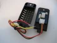
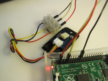
The digital communication with this sensor is more complex. In the datasheet, it is described as single bus communication. The 0’s and 1’s are not communicated by voltage, but by timing (in microseconds) on how long the voltage stays up (see C source code for more information). Luckily the link above contained a link to an executable. The purpose was to do a quick test if this sensor can be used with Raspberry Pi, and yes it works.

The execution was done with DHT22 or AM2302 as parameter

pi@raspberrypi ~ $ sudo ./Adafruit_DHT 22 4
Using pin #4
        Data (48): 0x1 0xcd 0x0 0xf1 0xbf
Temp =  24.1 *C, Hum = 46.1 %
pi@raspberrypi ~ $ sudo ./Adafruit_DHT 2302 4
Using pin #4
Data (48): 0x1 0xc8 0x0 0xf4 0xbd
Temp =  24.4 *C, Hum = 45.6 %
pi@raspberrypi ~ $ sudo ./Adafruit_DHT 22 4
                Using pin #4
Data (48): 0x1 0xc9 0x0 0xf2 0xb4

I opened the cover, but unfortunately the connector is not compatible (inch vs metric systems).

am2301

humidity-sensor

Case: I2C: Gyroscope and Accelerometer readings (MPU-6050)

In this case we are following a set of instructions (see Sources below):

Sources:

Links:

Verifying I2C connection:

pi@raspberrypi ~ $ sudo i2cdetect -y 1
     0  1  2  3  4  5  6  7  8  9  a  b  c  d  e  f
00:          -- -- -- -- -- -- -- -- -- -- -- -- --
10: -- -- -- -- -- -- -- -- -- -- -- -- -- -- -- --
20: -- -- -- -- -- -- -- -- -- -- -- -- -- -- -- --
30: -- -- -- -- -- -- -- -- -- -- -- -- -- -- -- --
40: -- -- -- -- -- -- -- -- -- -- -- -- -- -- -- --
50: -- -- -- -- -- -- -- -- -- -- -- -- -- -- -- --
60: -- -- -- -- -- -- -- -- 68 -- -- -- -- -- -- --
70: -- -- -- -- -- -- -- --

pi@raspberrypi ~ $ sudo i2cget -y 1 0x68 0x75
0x68

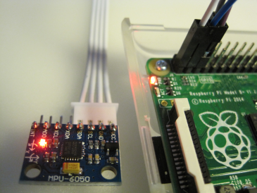
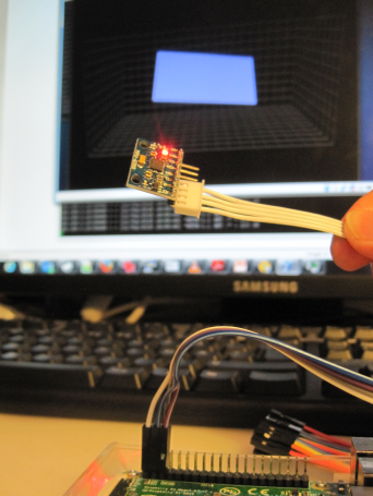
The picture below shows the sensor and 4 cables used to connect it with Raspberry Pi.

gyro1

Copying the source code into gyro.py, and executing it (for the source code, see links above):

pi@raspberrypi ~ $ sudo ./gyro.py
gyro data
---------
gyro_xout:  -141  scaled:  -2
gyro_yout:  328  scaled:  2
gyro_zout:  63  scaled:  0

accelerometer data
------------------
accel_xout:  4628  scaled:  0.282470703125
accel_yout:  -296  scaled:  -0.01806640625
accel_zout:  15256  scaled:  0.93115234375
x rotation:  -1.06367143706
y rotation:  -16.8724967644

After this, xubuntu VM was used to execute the OpenGL 3D program (level.py) to demonstrate the orientation.

gyro2

Conclusion

Already “now” there are several working examples for testing and playing with “Internet of Things” 🙂 . Well, here “now” actually means 2-3 years back. Now there is even more complex examples. But to get started, it is good to start from the basics…

Posted in DIY, For Fun or Interest, Gadgets, Hobbies and Other Interests, Innovation and new tech, Internet of Things and M2M, Raspberry Pi, Tests | Comments Off on Raspberry Pi and physical interfaces, part 2

Fritzing, tool for documenting Raspberry Pi projects

Fritzing is an open source tool, which is great for documenting your Raspberry Pi projects. Their library contains several electronic parts, and if needed, one can create own components too. For advanced usage, one can even order PCBs (Printed Circuit Board).

The primary view is the breadboard view as shown below.

fritzing01

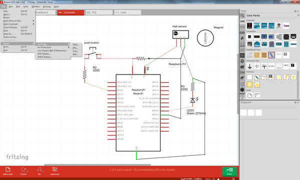
The schematic view is automatically created & updated while working on the breadboard side. After breadboard is ready, one can finalize the schematic into a better looking arrangement.

fritzing02

The examples above are related to blog Raspberry Pi and physical interfaces, part 2 . The source file is here (it is zipped, please unzip first to get the “.fzz” file)

Posted in Anvanced Tools, DIY, For Fun or Interest, Hobbies and Other Interests, Innovation and new tech, Internet of Things and M2M, Raspberry Pi, Robotics, Tools | Comments Off on Fritzing, tool for documenting Raspberry Pi projects

Raspberry Pi and physical interfaces

Raspberry Pi contains several GPIO pins, which can be used as digital input or outputs (GPIO = General-purpose input/output).

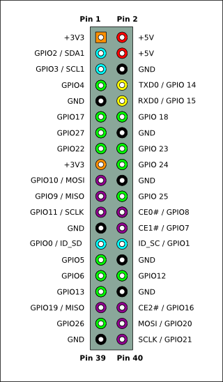
For example, if GPIO4 is defined as output, then setting the output value to 1 provides 3.3V into that physical pin 7. If GPIO4 is defined as input, then it can read values 0 or 1. Value 1 means that there is a voltage detected on the physical pin 7.

The same physical connector also has pins for other interfaces, for example for a serial interface SPI. (MOSI, MISO, SCLK). The physical pins for SPI are 19, 21, 23-26.

SPI is usefull for reading analog values from outside world via ADC (Analog-to-digital converter). Some ADC chips contains the SPI and can therefore be directly used with Raspberry Pi.


Pi-GPIO-header

However, if one wish to connect Raspberry Pi with physical devices, it is easier to buy one of the expansion boards. For example, Gertboard.

In this blog, we take a simple look on some examples and are using python for programming. Please see RPi GPIO Code Samples for more details on programming languages available, for example wiringPi is very widely used from different programming languages.

Using push button to turn on LED

This is demonstrating on how to use GPIO. This is following the instructions: Reading and writing from GPIO ports from Python.

Main components:

  • push button, 1 LED, 2 resistors (800 ohm), (GPIO connector cable)

RPI-button-led

The interactive python, ipython, was used with the following code:

import RPi.GPIO as GPIO
GPIO.setmode(GPIO.BCM)
GPIO.setup(4, GPIO.IN, pull_up_down=GPIO.PUD_DOWN)
GPIO.setup(25, GPIO.OUT, initial=GPIO.LOW)
GPIO.add_event_detect(4, GPIO.BOTH)
def my_callback(channel):
   GPIO.output(25, GPIO.input(4))
GPIO.add_event_callback(4, my_callback)

Note, GPIO4 is physical pin 7, and GPIO25 is physical pin 22.

When change is detected on GPIO4, then my_callback is executed and output of GPIO25 is set to same value as is read from GPIO4.

After each run, it is good to give command GPIO.cleanup()

Measuring the temperature

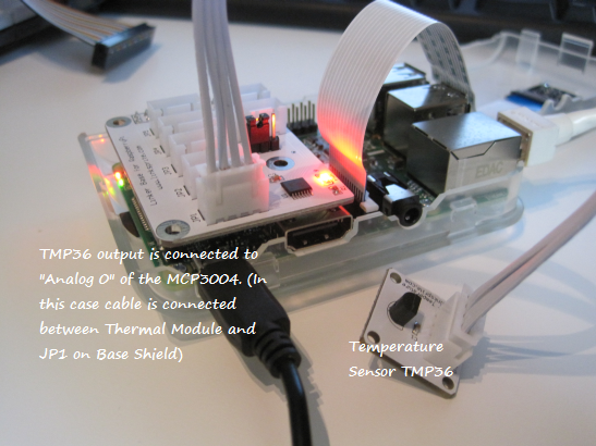
In this case ADC is used to measure the output voltage from a temperature sensor. The value from ADC is read via SPI.

Local PC store had components from linksprite. The instructions at the manufacturer site are followed: How to use Linker kit Base Shield for Raspberry Pi with ADC Interface with Python Code. (It is possible to make this test by using TMP36 and MCP3004 directly instead of using ready made components)

RPI-ADC-TMP36-text

The original instructions were giving voltage values. The code was modified to get both voltages and temperatures:

import spidev
import time
import datetime

adc_channel = 0
spi = spidev.SpiDev()
spi.open(0,0)

def readadc(adcnum):
# read SPI data from MCP3004 chip, 4 possible adc's (0 thru 3)
  if adcnum >3 or adcnum <0:
     return-1
  r = spi.xfer2([1,8+adcnum <<4,0])
  adcout = ((r[1] &3) <<8)+r[2]
  return adcout

while True:
    value=readadc(adc_channel)
    volts=(value*3.3)/1024
    ts = time.time()
    st = datetime.datetime.fromtimestamp(ts).strftime('%Y-%m-%d %H:%M:%S')
    print st
    print("SPI: %4d/1023 => %5.3f V" % (value, volts))
    temp=(1000*volts-500)/10
    print("                = %4.1f degree C" % (temp))
    print("-----------------------------------------------------")
    time.sleep(5)

When executed, it gave the following printout

pi@raspberrypi ~ $ python ./temperature.py
2015-07-05 17:22:10
SPI:  231/1023 => 0.744 V
                = 24.4 degree C
-----------------------------------------------------
2015-07-05 17:22:15
SPI:  231/1023 => 0.744 V
                = 24.4 degree C
-----------------------------------------------------

Please note, that the reading from serial interface (SPI) is done with the command spi.xfer2().

Serial connection to Raspberry Pi

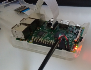
Raspberry Pi’s GPIO contains pins for serial communication, and it can be used to connect to the operating system. An USB TTL cable was used. The instructions from Adafruit’s Raspberry Pi Lesson 5. Using a Console Cable were used. Please note that RS232 and TTL has different voltages. (If you intend to use USB-RS232 cable, then an additional RS232-TTL converter is needed as well.)

RPI-USB-TTL

Continuation

Please see part 2.

Posted in DIY, For Fun or Interest, Gadgets, Hobbies and Other Interests, Innovation and new tech, Internet of Things and M2M, Raspberry Pi, Tests, Tips | Comments Off on Raspberry Pi and physical interfaces

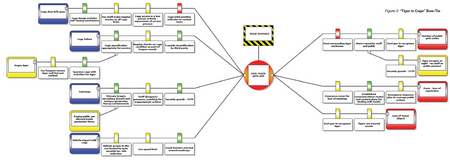
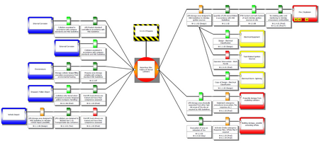
“Tiger in the cage” examples, bow-tie analysis as part of risk assessment

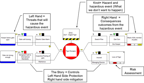
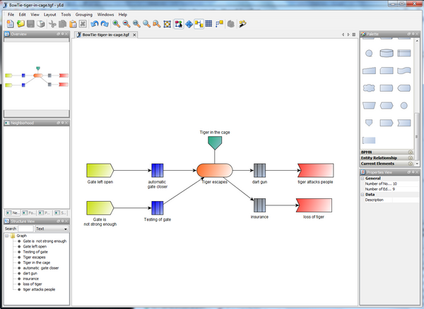
Bowtie analysis might be an helpfull tool for risk assessment. I used yEd to create my own bowtie (see the source at the end).

Bow tie analysis in the ISO 31010.

Bow tie analysis is a simple diagrammatic way of describing and analysing the pathways of a risk from causes to consequences. Bow tie analysis is used to display a risk showing a range of possible causes and consequences.

bowtie-in-iso-31010

Tiger in the cage examples

Bowtie-tiger-example01

Bowtie-tiger-example03

Bowtie-tiger-example04

Additional material

Source for bowtie in cage for yEd tool

It is possible to create bowtie diagram in yEd tool.

To get started, the source for the example below is here (unzip first).

Bowtie-tiger-example06-yed

Posted in Basic Tools, DIY, Security Management, Security Threats, Security Training, Awareness and Reports, Tests, Tips, Tools | Comments Off on “Tiger in the cage” examples, bow-tie analysis as part of risk assessment